


Vision Guided Robotics
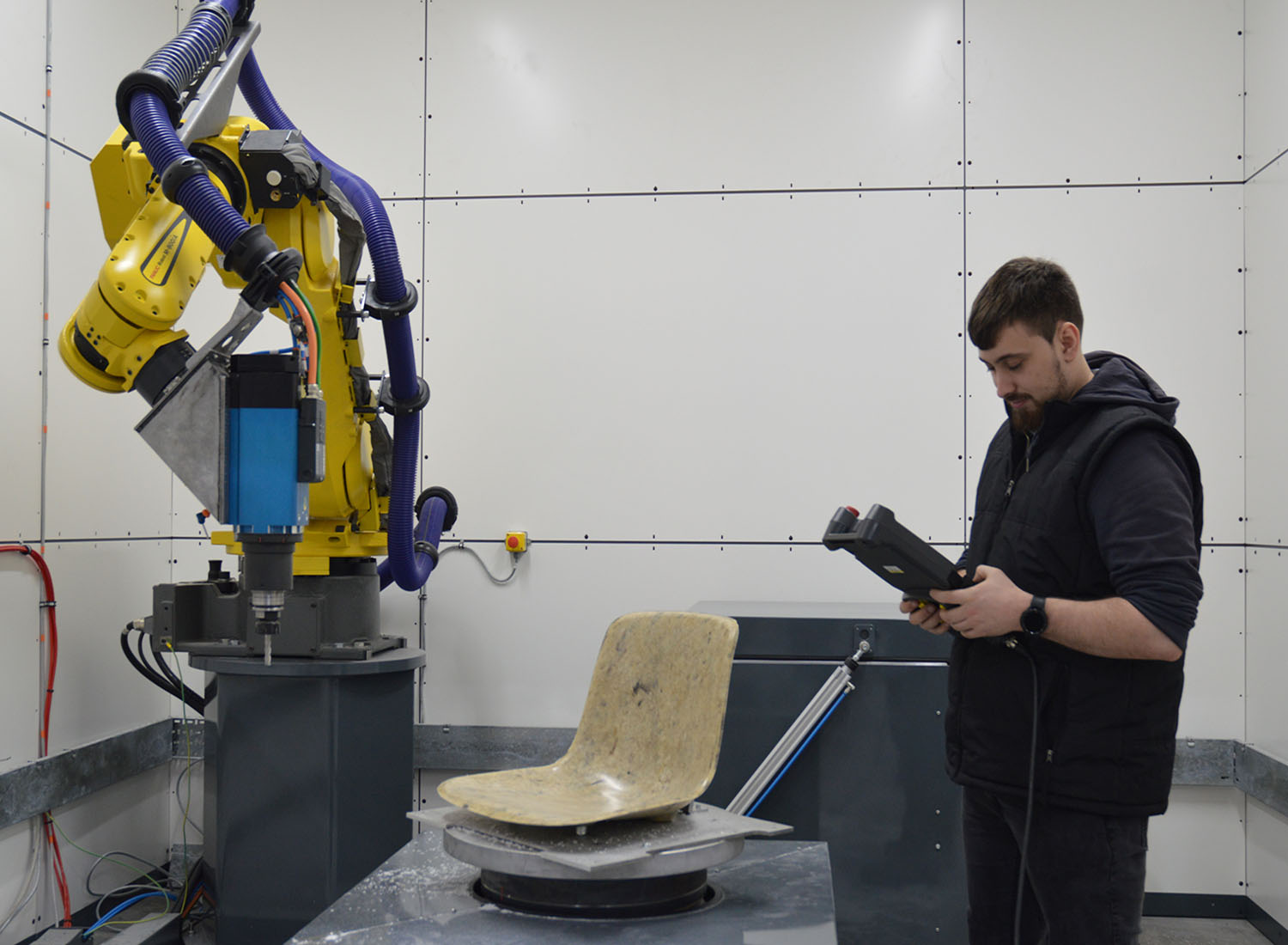
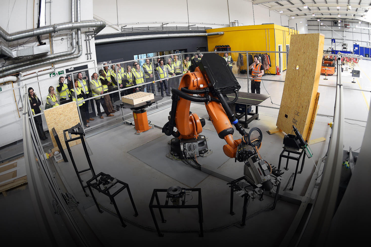
One significant area of Loop Technology expertise is in vision guided robotics and working with computer vision to adapt robotic pathways. Through integrating machine vision systems with automation platforms, we enable accurate, adaptive robotic movement in dynamic industrial environments and create systems that complete advanced manufacturing tasks with speed, repeatability and accuracy. It includes the use of advanced 3D cameras, image processing, unique software solutions, sensors and Artificial Intelligence. Our vision guided robotic solutions are used for applications as varied as object recognition, labelling, motion targeting, measurement, inspection, tracking, scanning and process optimization.
3D Path Planning

Loop Technology are specialists in 3D path planning and enabling robots to follow precise 3D trajectories towards targets and around obstacles. We use highly advanced 3D cameras including structured lights scanners, to generate optimal robotic programs from captured scene data. Leveraging our in-depth knowledge of environmental mapping, 3D modelling, motion planning algorithms, CAD-based and AI path generation tools as well as real-time adaptation, we create solutions that deliver precise, automated robotic operations into complex and unstructured industrial environments.
Loop Technology products that utilise our 3D path planning expertise include RealPATH, a unique software solution that automatically generates robotic pathways and bypasses the need for offline programming. Additionally, there is IdentifEYE, a dynamic labelling system that uses 3D vision.
Related Products

IdentifEYE

RealPATH
Localised Correction
Loop Technology apply localized correction techniques in a range of our advanced manufacturing solutions in order to increase system accuracy via the measurement of location from image data. Localized correction requires expertise in a variety of domains depending on the application but includes in-depth knowledge of control loops, vision systems, applying error-detection, sensors, real-time feedback and dynamic adjustment. It is used in automated welding, pick-and-place and applications that require millimetric precision. Localized correction is used in Bravura, a revolutionary Loop Technology product that can enter confined spaces such as aircraft wing boxes to complete assembly and sealant tasks.

Calibration & Metrology

Loop Technology offer automated solutions and expertise in calibration tasks including using machine vision and robot kinematics to determine an accurate Tool Centre Point (TCP) as well as base transforming DH parameters for a robot. Calibration enables precise control of a robotic system, reduces error and increases reliability in a variety of manufacturing tasks that require high precision.
We use industrial vision systems to measure object dimensions, verify tolerances, inspect parts and surface characteristics. Loop Technology has extensive experience in real-time pose estimation, using 3D vision for measuring and tracking the positioning of objects and robots in industrial environments.
We also specialize in offline programming and simulation capabilities. For instance, we are able to apply kinematic correction to a robotic system at the post processor stage, allowing the customer to benefit from increased system accuracy without modifying the controller.
Related Products

VerifEYE
Composite Inspection
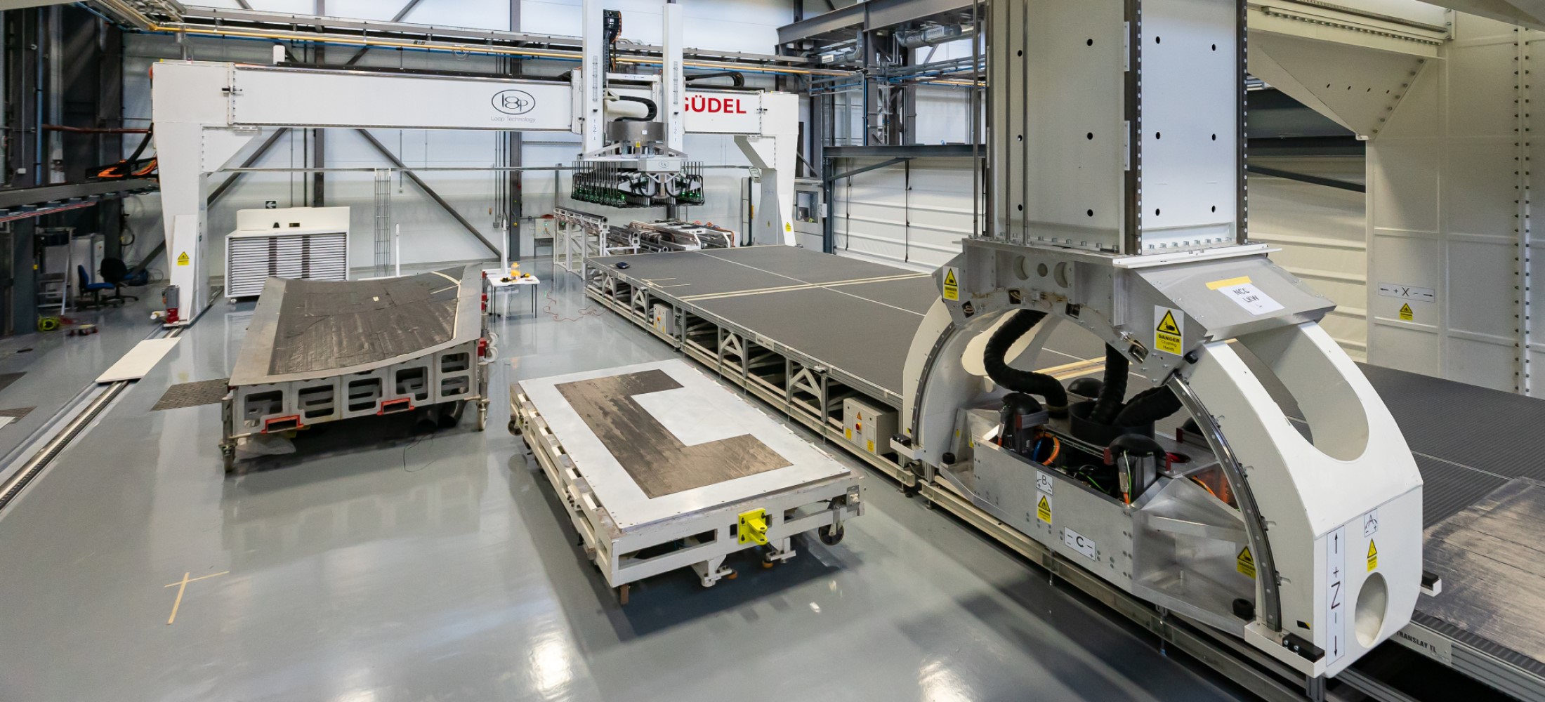
Pioneering carbon fibre and automated composite inspection techniques have become a key competence within Loop Technology’s range of services and products.
We have developed systems to meet the stringent quality standards of the aerospace sector, though they are applicable to a number of other industries. FibreEYE provides a comprehensive inspection ecosystem that operates in two crucial domains: in situ material defect detection during manufacturing, and precise placement verification during automated layup.
This technology combines advanced imaging with Artificial Intelligence. By correlating data from a 3D laser profiler with precise positioner information, the segmentation algorithm is able to distinguish between material layers and reconstruct complex 3D layouts with minimal gaps to facilitate highly advanced inspection and verification in composite manufacturing.

Related Products

FibreEYE
If you are interested in talking to us about our Vision Guided Robotics solutions, please contact us.
Showcase


